Sizing Printed Circuit Heat Exchangers: A Comprehensive Guide
Printed circuit heat exchangers (PCHEs) are a cutting-edge class of compact, plate-type heat exchangers engineered for extreme conditions. They consist of stacks of thin metal plates (often stainless steel or nickel alloy) into which fine microchannels are chemically etched, then diffusion-bonded into a solid block. This novel construction delivers an exceptionally large heat-transfer surface area in a small footprint.
SHPHE's PCHEs can operate at pressures up to 1000 bar and temperatures as high as 850–900°C, conditions under which conventional exchangers fail. The diffusion-bonded microchannel network also ensures high strength and corrosion resistance. The result is a heat exchanger with remarkably compact size and high thermal efficiency – for example, a footprint about 5–10 times smaller than a comparable shell-and-tube unit.
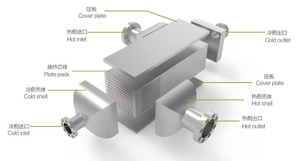
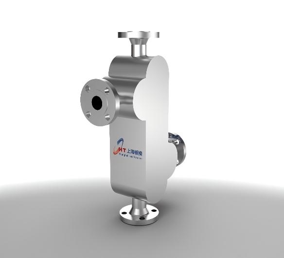
Figure: Construction of a Printed Circuit Heat Exchanger. Thin plates with etched microchannels are stacked and diffusion-bonded into a solid block. Cover plates and header shells form inlet/outlet manifolds for the hot and cold fluids.
The illustration above shows a typical PCHE assembly. Cover plates attach to inlet and outlet shells, and the core is a stack of channel plates. Each channel plate carries either the hot or cold fluid, separated by thin metal walls. Fluids can flow in counter-current or cross-flow paths, maximizing the log‑mean temperature difference. Because the plates are bonded into one monolith, there are no gaskets or joints between plate layers – eliminating leak paths and enabling operation at ultrahigh pressures.
Printed Circuit Heat Exchanger Applications
Oil & Gas: In liquefied natural gas plants and regasification units, PCHEs serve in precooled methane cycles, end-flash gas recovery, boil-off gas handling, and vaporizer duties. The cryogenic performance (down to –196°C) and high-pressure capability make PCHEs ideal for fuel gas heaters and heat recovery in floating regasifiers.
- Hydrogen Fueling and Processing: Rapid hydrogen fueling stations rely on fast precooling of high-pressure H₂ to maximize fill rates. PCHEs (especially with specialized 3D-etched channels) are used to pre-cool hydrogen from 700 bar to storage conditions, reducing pump power and wait times. More broadly, hydrogen liquefaction and processing can leverage PCHEs’ high-pressure resilience.
- Chemical and Petrochemical Plants: PCHEs are time-tested in high-pressure hydrocarbon processing, refining, and petrochemical duties. They handle duties like gas dew-point control, reactor interstage cooling, acid gas cooling, and condensation in processes requiring stringent cleanliness. Their small fluid inventory and high thermal effectiveness suit them to clean, critical services. (Nickel-alloy PCHEs, for example, are widely adopted in chemical processing to resist harsh fluids and high temperatures.)
- Power Generation: In advanced power cycles, PCHEs are used in recuperators and generators. For supercritical CO₂ cycles, where all streams are at 200–300 bar or higher, PCHEs can withstand the ~600°C temperature glides and massive pressure differences. They are also used in nuclear power (steam generator replacement), and gas turbine fuel gas heating. Their ultrahigh pressure rating (up to ~1250 bar on some designs) makes them attractive for novel cycles.
Renewable Energy and Storage: PCHEs are gaining attention for concentrated solar power, long-duration thermal storage (molten salts, etc.), and carbon capture systems, where high cycle efficiency and compact heat exchange are critical.
Key Considerations in PCHE Sizing
- Thermal Duty (Heat Transfer Requirement): First, calculate the required heat duty Q from process data (mass flow rates, specific heats, and temperature change of the hot and cold fluids). Also determine the log-mean temperature difference (LMTD) or required outlet temperatures. The heat duty and LMTD set the needed overall heat transfer area via the relation
where U is the overall heat transfer coefficient. - Fluid Flow Rates and Velocity: Given the mass flow rates of each fluid (hot and cold sides), choose initial channel dimensions to compute velocity. For example, if each channel has cross-sectional area , fluid velocity . The velocity determines the flow regime (Reynolds number ) and thus the heat transfer and pressure drop. PCHE microchannels are typically on the order of 0.4–4 mm hydraulic diameter, so flows may range from laminar to turbulent depending on rate and fluid.
- Channel Geometry and Configuration: Decide on channel shape, width (), and length. PCHE manufacturers often provide catalogs of channel patterns (straight, zigzag, wavy, 3D, etc.) and plate corrugation profiles. Narrower channels raise surface area (increasing heat transfer) but also increase pressure drop. The selected geometry must satisfy pressure drop limits while delivering the required heat transfer. Because chemical etching is very flexible, PCHEs can implement complex serpentine or distributor patterns impossible in simple fin plates. The product parameters might guide initial choices – for example, SHPHE lists typical channel gaps from 0.4 to 4 mm and plate thickness 0.5–2 mm.
- Heat Transfer Coefficient Calculation: Use correlations to estimate the convective heat transfer coefficient h on each side. For many PCHE designs (semicircular channels of a few millimeters), Nu and friction factor correlations are available from literature or CFD data. For instance, one study gives for 2 mm semicircular channels:
- Area and Channel Count: Once U is estimated, solve for the total heat transfer area needed. In a PCHE, the area comes from the sum of all channel walls. If each channel plate has parallel channels of width and length , and there are plates, then the total area is approximately (where accounts for asymmetry if any). From this, one can solve for the required and given practical plate dimensions. For example, if a 0.5 m² effective area is needed and each channel contributes 0.01 m², then roughly 50 channel-plates must be stacked.
- Pressure Drop Estimation: Calculate the pressure drop on each side. For a given channel, Darcy’s law gives . Here
is the mean velocity in the channel and the friction factor from the correlation above. Because channels are small, pressure drop can be significant – engineers must ensure stays within the allowable limit. If the drop is too high, one can increase channel size, reduce channel length (by adding more parallel channels/plates), or choose a different flow path geometry. - Material and Mechanical Constraints: Select plate material and thickness based on pressure and corrosion requirements. A industrial PCHE’s plate thickness must withstand the full design pressure; for example, SHPHE specifies plate thickness from 0.5–2 mm for pressures up to 1000 bar. Materials like SS316L, Inconel 625, titanium, or Hastelloy are common to resist high temperature or corrosive fluids. Very high pressures may require thicker plates or high-strength alloys, which reduce channel size or area, so this trade-off must be iterated.
- Iteration and Optimization: Because the factors above are interdependent, sizing is usually iterative. One typically adjusts channel gap or count and recomputes U and until both the thermal duty and hydraulic constraints are met. Computational tools or manufacturer software often aid this. In critical cases (sCO₂ cycles, for example), a detailed simulation may be used to finalize geometry.
Define requirements: Gather hot/cold inlet/outlet temperatures, mass flow rates, allowable pressure drops, and required duty
. Preliminarily select channel dimensions: Choose a channel width (e.g. 1–3 mm) and plate corrugation form.
Compute velocity and Reynolds number: , .
Estimate heat transfer coefficients: Use Nusselt correlations (Nu vs. Re) to get and for each side.
Compute overall
: Combine , , and wall conduction. Calculate required area: .
Determine channel count/length: Use area formula to find and that match the plate size.
Check pressure drops: Compute for each side.
Adjust geometry: If is too high or U too low, modify channel width, plate count, or flow path (add bends, change pattern) and repeat.
Validate mechanically: Ensure wall thickness and material meet ASME/PED codes for the design pressure and temperature.
Throughout this process, it is crucial to respect manufacturing constraints. For example, chemical etching can create very intricate channels (serpentines, multi-pass circuits), but excessively thin walls (<0.2 mm) are impractical to etch and bond. SHPHE’s guidelines suggest plate thicknesses in the 0.5–2 mm range for most PCHEs.
Comparison to Shell-and-Tube and Other Type of Exchangers
PCHE sizing is more intricate than for conventional exchangers, but it brings significant benefits. Shell-and-tube heat exchangers (STEs) are designed using well-known correlations and often use the LMTD or NTU methods in textbooks. Their large tubes and shells make analysis simpler (tubular Nusselt and friction factor charts, straight calculations). However, STEs are bulky and heavy. In contrast, a PCHE’s microchannels demand detailed heat-transfer and CFD analysis at the channel level, which is more complex mathematically but yields a much smaller unit.
Plate-fin (finned plate) exchangers are also compact, but they have limitations. A plate-fin uses alternating fin stacks for each fluid, formed mechanically. Mechanical forming constrains fin shapes (sharp bends and extreme corrugations are hard to press). Chemical etching in PCHEs is far more flexible: any channel pattern that can be printed on a mask is possible, including very complex serpentine and distributor shapes. Thus, PCHEs can achieve higher surface density or special flow arrangements (e.g. multi-pass compact designs) that plate-fin cannot.
In terms of performance, PCHEs typically beat STEs and PFHEs in compactness and efficiency. Studies report that PCHEs can fit 4–6 times the heat transfer area in a given volume compared to a shell-and-tube, achieving up to ~98% thermal effectiveness. The dense microchannels also give lower fluid inventory: one case replaced a 70-tonne shell-tube unit with an 11-tonne PCHE. The smaller inventory further reduces energy losses, pipe runs, and even the required size of safety relief equipment.
On a Final Note
Sizing a PCHE requires careful attention to flow rates, thermal duty, channel geometry, and pressure-drop constraints – more so than conventional exchangers – but this effort unlocks the PCHE’s unique benefits. By following the outlined approach, engineers can design a PCHE that meets the required heat load in a fraction of the space. PCHEs excel in extreme conditions (up to 1000 bar, 850°C) where other exchangers fail. Whether for LNG, hydrogen, chemicals, or power generation, the key to leveraging this technology is precise sizing and material selection.
Shanghai Heat Transfer Equipment Co., Ltd. specializes in the design, manufacturing, installation, and service of plate heat exchangers and complete heat transfer systems.
If you need further consultation and discussion, please feel free to contact us.
Email: info@shphe.com
WhatsApp /Cell: +86 15201818405


